Hi, so tonight we tried to do the first dry run on my ski press and we ran into a few issues. The pins we had holding the side bars in bent under pressure approximately 40lbs psi. Since the pins were 1/4inch cold roll steel I'm thinking re-drill the holes in the frame to 3/8 and use bolts instead.
The other issue Was that at the curve towards the tips it didnt look like the hoses were pressing down enough. I'm thinking about adding material to the curve on the top mold. I was talking with the guy who was helping me and he said that we should add pressure to get them to fill the cavity but I'm concerned about the frame and the hoses. The hoses I have are only rated to 70 psi max. I'm not exactly sure what pressure I want to press at either. I'm using the QCM emv-0043.
woah danger.
Prolly don't want to go past 45 psi. Did you do an analysis on the frame or wing it?
Metal cassette and a cat track and a good inverse copy for your top mold that is slightly smaller, length wise, to account for the materials in between will deliver better pressure in the tips i think.
Yeah we winged it, slowly applied pressure. This is about what I was thinking we would do pressure wise before we started and I don't want to go too much past it if at all. You do make a good point about the length on the top mold, I think it may be possible to re-cut it so its a bit shorter and matches to the bottom mold better.
Underdog wrote:Yeah we winged it, slowly applied pressure. This is about what I was thinking we would do pressure wise before we started and I don't want to go too much past it if at all. You do make a good point about the length on the top mold, I think it may be possible to re-cut it so its a bit shorter and matches to the bottom mold better.
Just cut the top mold in half, and take an inch out or so. You don't need to fix the two halves together either, since once its under pressure it'll hold itself together
I'm confused how your steel bent like that though. I mean yeah, 1/4" is a bit small, but did it slip off or something? It looks bent like it deflected an inch or something.
How are the ends of your press fixed? Just more vertical supports like that, or is it welded to something else, or?
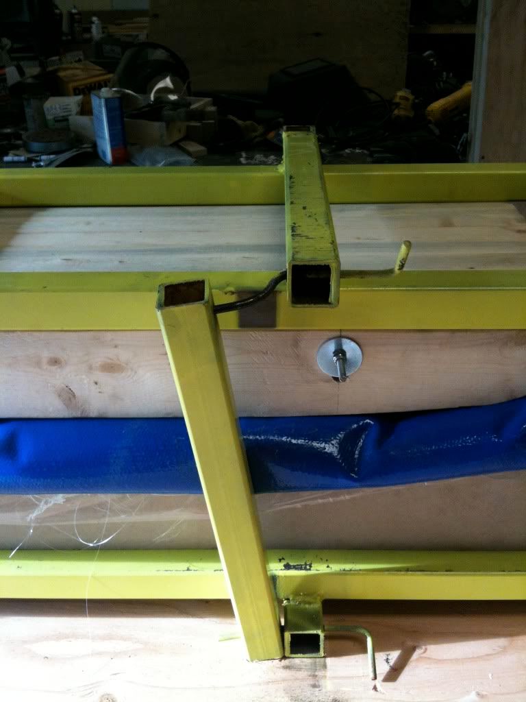
I think the steel bent like that because since the pins had freedom of movement the steel slipped on them as it was pulling. Bolts should fix that movement and be stronger. I really like your idea of just cutting the mold in the middle to make it shorter. Here's the best picture of the complete frame I have at the moment. There are 4 of these hoops on it. One side is pinned(bolted soon) for side access.
How we did ours was two flanges, on on other side of the vertical supports, with a pin through them. That way the vertical support can't go side-to-side.
Bolts are certainly easier, just a bit more work during the layup to get it all closed up (and then again to open it back up).
Here's the best picture I can find showing the flanges on our press
Unless your press is perfectly square and aligned it will twist slightly when you apply pressure, and your supports will be loaded in all sorts of weird ways rather then in pure tension. A bolt would likely take care of that, but then you have an odd loading situation on the head of the bolt, shear and tension in some unkoen combination.
Weld on some tabs like twizzstyle did to keep everything in alignment, then pick up a few of these:
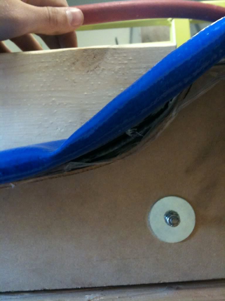
I had the same problem with the hose not bending into the tip area. My problem was the the tip block was too tall so I cut about an inch off and the bottom mold needed to be raised. However your tip block looks ok, as far as I can tell from the pic. Also your opening looks much smaller than mine so I'm sure you don't need to raise the bottom mold. As far as the top mold goes, you got good advice already.
Definitely use a cat track.
If you're going to use pins or bolts use hardened steel #8, and bigger than 1/4 if you can.
He does a grade 5 vs 8 1/4" shear calculation, and there is a table for a bunch of fasteners. Long story short, use grade 8 over 5 if using bolts.
Grade 8 might "snap" during a shear failure, but if it gives you an extra 1/3 ton capacity and brings your factor of safety (F.S.) into the correct range then who cares? For a press you want at least a F.S. of 2, or the press should be capable of holding 2x the amount of pressure that you intend on running at.
Well I re-drilled all the holes last night to 3/8 and put grade 8 bolts in. I do realize that they are designed for tensile forces primarily but I don't think in this application there is nearly enough force being generated to shear them especially since each bolt is running through 4 holes.
Underdog wrote:Well I re-drilled all the holes last night to 3/8 and put grade 8 bolts in. I do realize that they are designed for tensile forces primarily but I don't think in this application there is nearly enough force being generated to shear them especially since each bolt is running through 4 holes.
Is the threaded portion of the bolt being subjected to the shear? IIRC bolts are not rated for a shear load on the threaded portion. 3/8 is kinda small as well.
Plus, I still think you have some weird loading due to either the bladder sticking out the side or just because the vertical support is only held on one side. I hope it works out for your, but honestly you wouldn't catch me near that thing while it is under pressure...
Have you ran the numbers? Pressure is a dangerous thing. Yes the bolts are going through 4 holes, but there is ONE shear point - in between the two bars. That's where they would fail.
Hose pressure times surface area, divided by the number of bolts (16? or is the back part welded)