thanks and sliding inserts

For discussions related to ski/snowboard construction/design methods and techniques.

Moderators: Head Monkey, kelvin, bigKam, skidesmond, chrismp

markhr
Posts: 22
Joined: Thu Oct 27, 2005 12:47 pm

thanks and sliding inserts

Post by markhr »

Thanks for the truly awesome website.

does anyone know where to get sliding inserts like those on capita snowboards? If so, are they individual or could you have 3 parallel tracks with multiple sliding inserts? That is, to allow for alpine and tele bindings.

Image
User avatar
bigKam
Site Admin
Posts: 538
Joined: Tue Feb 01, 2005 5:15 pm
Location: Park City, Utah
Contact:

Post by bigKam »

markhr: welcome!

the sliding inserts is a neat idea, especially the idea about three tracks for tele and alpine... i don't know where to get them, but i wouldn't image that they would be hard to find. keep us posted if you locate some...
markhr
Posts: 22
Joined: Thu Oct 27, 2005 12:47 pm

Post by markhr »

BK

thanks -just spent 15 minutes banging my head against the burton wall of silence. It seems that, judging by the 05/06 pictures, Capita no longer use sliding inserts however Forum do. Burton owns Forum and Burton wouldn't give the supplier information out at all (not to me anyway).

So, if someone else has a board shop/industry contact they can use please do as all I got was a wall of silence from Burtons switchboard.
markhr
Posts: 22
Joined: Thu Oct 27, 2005 12:47 pm

Post by markhr »

so far so ok - I've got an e-mail address of the person Capita paid to license the technology. I don't know if she owns it or if she's an agent for the inventor yet.

The better news is that the slides are individual and can be made to any length. With that in mind a three parallel slide setup at heel and toe would be cool. That'd mean being able to use the same skis for powder(rear mount) and park(middle or balance point mount) with just an allen key/posidrive bit to make the change on mountain.
collin
Posts: 105
Joined: Sun Oct 23, 2005 10:19 pm

Post by collin »

I was playing around with the eMachineshop.com CAD software and a milled 6 inch aluminum track would cost ~$18 (goes down to ~$15 apiece if you order 10+). Not too expensive, but I haven't been able to figure out how you design a part that has cuts on two surfaces. The part I sketched didn't have tabs on the bottom edge to hold it in the core, so a design with those tabs would be a little more expensive. That said, if you had access to a milling machine it would be super easy to make a track. It's even simple enough, and you don't need 1 mil accuracy, that you could mill it on a drill press if you had 1 axis of horizontal movement.

Are those black squares that say "FG" plugs in a hole big enough to let you replace the inserts incase you stip an insert?

Are the widths between the mounting holes on alpine and tele bindings the same? Could you actually swap bindings? I was thinking about using simple patern of inserts on the ski and mounting an HDPE plate with more inserts in it that match up to a binding.

Anybody remember "Ess var" alpine bindings maybe 10 years ago? They did the whole shift forward/backward thing with a fixed mount to the skis. I feel really old when I remember my friends "cool" skis one season being a pair of Hart bump skis with Ess var's.
User avatar
hose-man
Posts: 167
Joined: Tue Aug 02, 2005 11:17 am

Post by hose-man »

collin wrote:
Are the widths between the mounting holes on alpine and tele bindings the same? Could you actually swap bindings? I was thinking about using simple patern of inserts on the ski and mounting an HDPE plate with more inserts in it that match up to a binding.

Anybody remember "Ess var" alpine bindings maybe 10 years ago? They did the whole shift forward/backward thing with a fixed mount to the skis. I feel really old when I remember my friends "cool" skis one season being a pair of Hart bump skis with Ess var's.
That is one of the better ideas I've heard lately. Having a HDPE riser that fits your alpine bindings then having the tracks to move your tele pattern fore & aft would be pretty incredible.

Oh I remember the ESS bindings. I had some wicked pink ones & also some red ones on red, white and blue K2 SL-race skis. 210 and straight as a board.

I bet those Hart bump skis were the F-16. That was about the right era. Kind of a glossy army green color.
markhr
Posts: 22
Joined: Thu Oct 27, 2005 12:47 pm

Post by markhr »

one idea is to use edges as the track

serrate edges on the lower side to prevent inserts slipping

Image

mounting the edges so that they don't compress into the channel on pressing or rip out on mounting might prove to be too much of a challenge for this method

I'm not sure how you'd machine a channel so it attaches to the core to prevent pull out? One idea is to make the channel with an I beam shape on the bottom and then glue it into the core before profiling

Image

Not sure about the FG bit but I'd say that's a good guess.

As far as choice of 3 channels goes I'd probably choose your favourite binding and work of those dimensions. 3 channels for most tele/alpine/tour bindings and 2 channels for Line reactors.
kohlrabi
Posts: 26
Joined: Thu Aug 25, 2005 8:52 pm

Post by kohlrabi »

I've never seen sliding inserts and I'm having a difficult time visualizing them.

have you got a CAD drawing by any chance, collin?


I'm working on getting access to a CNC milling center/CNC lathe. There is definately a possibility of getting some of these made up if I can find the machine time.
collin
Posts: 105
Joined: Sun Oct 23, 2005 10:19 pm

Post by collin »

have you got a CAD drawing by any chance, collin?
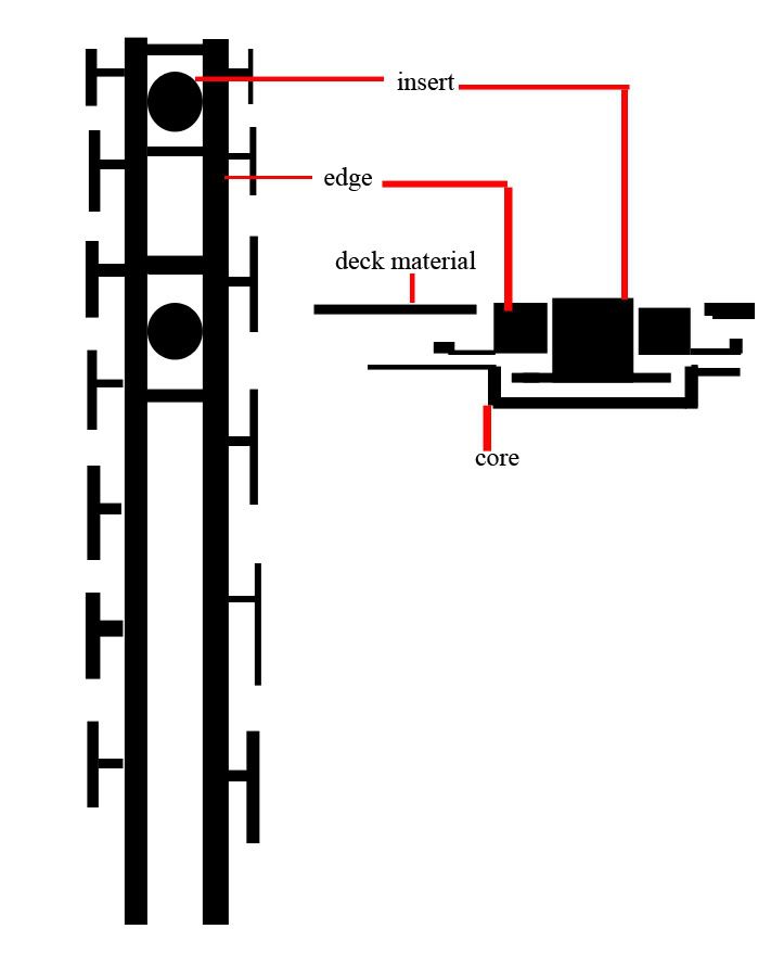
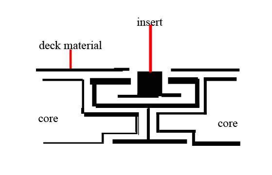
Yeah, no problem. Though I was just kinda guessing on the dimensions since I don't have any inserts, just playing around really. If somebody could tell me the distance between the two flat sides on the bottom of the insert, the diameter of the bottom (ie if the flat sides weren't there the diameter of the bottom flange), and the outside diameter of the threaded part.

Now that I think about it I realize that I mispoke when I said you didn't need high accuracy. Well you don't for most of the cuts. I'll work up a cad drawing later with some pics and maybe this will make a little more sense.
Guest

Post by Guest »

Well, I might as well put some pics up of what I was thinking would work. (Top and bottom respectively)
Image
Image

And here's an autoCAD file and an eMachineShop CAD file. Note: the dimensions in the CAD files mean NOTHING! , since like I said before I don't have any inserts to measure. Feel free to play around with them, or let me know what the dimensions should be and I can change it.

So here's how I think they should work. One thing is that the bottom needs to be covered before layup, to keep glue out of the track and water out of the ski. Since it doesn't have to be that strong I was thinking a thin aluminum plate attached with some JBWeld, being careful not to get any inside the track.

Now, I'm not sure what the best way to put them in the ski is. I'd say the best way would be so that the track ends up flush with the topsheet, covering it with a piece of tape (strong enough?) or metal temporarally glued in place (elmers?) to keep epoxy out. Though this means cutting matching holes in the top composite layer and the topsheet. Suggestions? Besides that I think it should be basically the same as using inserts. You could throw a few small magnets in beore layup to do the iron filings trick. Like inserts the thickness of your core and the depth of the track matter.

One concern I have is that using tracks like this would create a "dead spot" in the ski where it can't flex. Not that I think I could tell the difference.
collin
Posts: 105
Joined: Sun Oct 23, 2005 10:19 pm

Post by collin »

Damn it. I keep posting without logging in.
Broz

Freedom Groove

Post by Broz »

The name and number you probably got was Janice. Her and her dad were the original investors in Revalation (Rev) Snowboards, Hard 8 Manufacturing in Surrey (Vancouver), Canada and they were the money and manufacturing behind Capita the first few years before they moved it to Europe. Janice owns the patent on the Freedom Groove (shown above), and she has literally thousands and thousands of those sliders in storage in every color imaginable. She is completely out of the snowboard industry now, so I'm guessing she's waiting for more lucrative licensing agreements for the patent or it's simply not worth her time. I know her well, so if you need more information feel free to email me: info@logicsnowboards.com, but again, to be honest, she isn't just going to sell a few sliders...it's totally out of the question. If you are looking to license the Freedom Groove for production purposes, then you'll probably get a response.

Broz
www.logicsnowboards.com
markhr
Posts: 22
Joined: Thu Oct 27, 2005 12:47 pm

Post by markhr »

Broz

You got it in one. I got an e-mail address for her at hotmail but so far no reply. I'm pretty sure she'd make more money selling inserts at a premium to individual amateur ski/board makers than just waiting for a licensing deal where she has to give them away by the thousand. Especially if Forum boards are using their own version, i.e., not her's.
markhr
Posts: 22
Joined: Thu Oct 27, 2005 12:47 pm

Post by markhr »

There's full spec's and pic's at http://patft.uspto.gov/netahtml/search-bool.html - just do a search for "freedom groove".

edit for the groove - doh!
Last edited by markhr on Tue Nov 01, 2005 8:26 pm, edited 1 time in total.
Guest

Post by Guest »

That took me a little while. They weren't coming up searching for "freedom plate" but did for "freedom groove". Whatever.

The patents are numbers
6,786,502 ; 6,189,899 ; 6,015,161

Looking over them quickly, they all seem to be the same. Or at least they use the same sketches. Use this page to get pdf's if you actually want to look at them.

I haven't looked at them closely but three things jumped out at me.

One, they're made to flex with the board. If you want to make them flex with the ski, they've got to be thin. And I worry a little about them being made of aluminum if they're thin enough to flex well. How important do people think this is?

Two, there's a part the inserts fit into that keeps them the same distance apart. I honestly don't think this is important, but I could be wrong.

Three, the surfaces of the track and the inserts which meet are textured in some way to help keep the inserts from sliding. This is a very good idea, and could be implemented either an easy & ok way or a hard & very good way.

There is a pic on Forum's site of the ones they use (click on the little pic to get a big one). I think "carbon reinforced slots" mean that the slots in the core are reinforced.

Are people still interested in hashing out a way to make these?
Post Reply