school credit skis...The Recurve, or Maybe The ReCoast

Document your personal work here. Show photos, movies, and share your secrets.

Moderators: Head Monkey, kelvin, bigKam, skidesmond, chrismp

jlutz05
Posts: 38
Joined: Fri Aug 29, 2008 10:57 am

school credit skis...The Recurve, or Maybe The ReCoast

Post by jlutz05 »

So I convinced one of may professors here at Virginia Tech to give me credit hours for building a pair of skis or two.....awsome! Anyway I have acces to a really nice shop and high tech equipment such as CNC mills, laser-camms and such, so I am lucky in that sense.
I am trying to use take advantage of the CNC adn other precise tools to eliminate inconsistency. so most of my construction process pictures will be dealing with the CNC and possibly the lasercamm later.

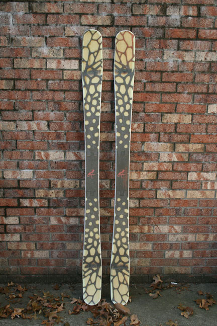
So here is the ski I designed....... 3d modle in Solidworks.

Image

Design was inspired by the conditions that I deal with sking in West Virginia. Sometime lots of pow, Sometime ice and groomers.

Here is my mold design.... 30 mm of camber in running length, I think around 6 or 7 cm of rise in the reverse camber tip and tail.


Image


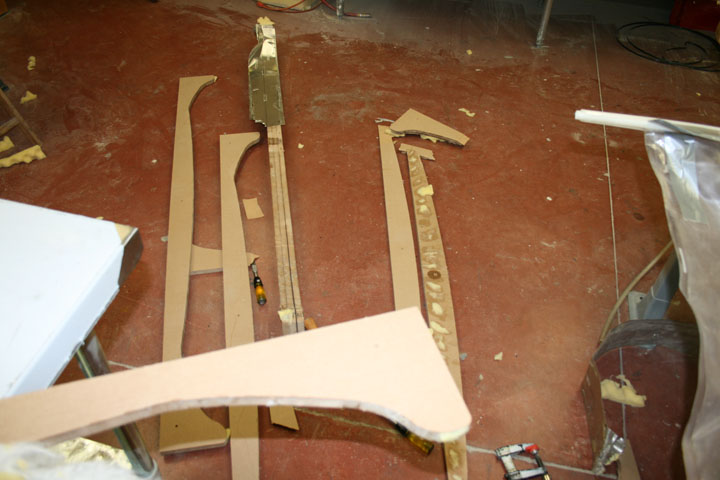
Used the CNC to Cut out 8 profiles.......will press one ski at a time.


Image

Image

[imghttp://media.newschoolers.com/uploads/cache/images/1223591036-636998-600x400-12235887799.jpg[/img]

Image

Image

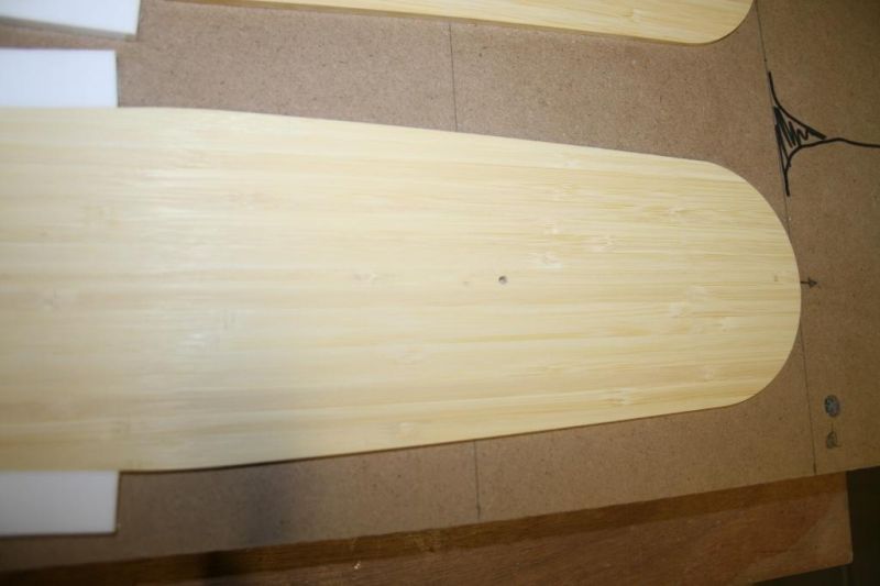
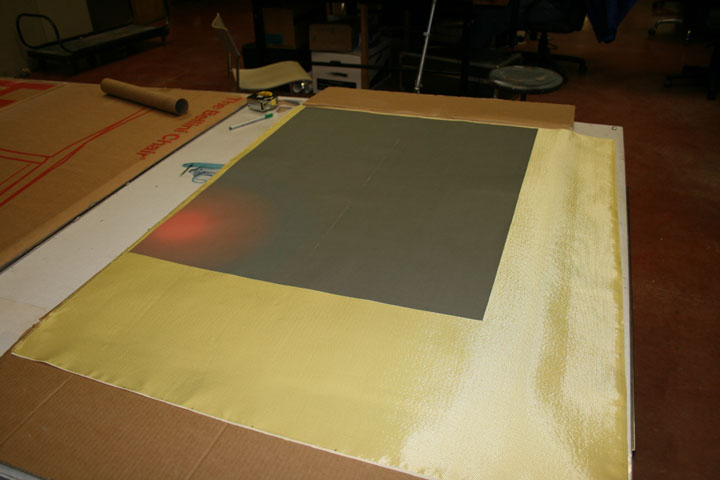
So I need to do some sanding and finishing plus stick some dowles through alignment holes and I will be done with that. What do you guys suggest for a top sheet on it?

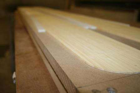
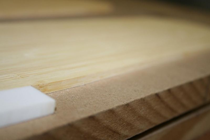
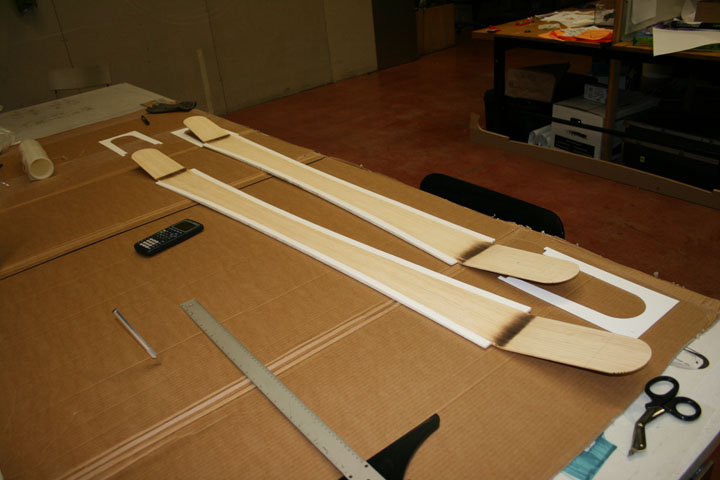
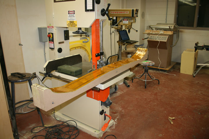
Next came milling out the core shape. Oh, and Im using bamboo planks for the material. Got it at 4windsbamboo.com. There will be a 1 cm base/core offset.


Image

Image

Image

Milled the base material next. I used double sided carpet tape to stick it to the CNC bed, it held it amazingly but did not want to come off and left residue on the base which I used goo gone to get off.

Image

Image

Image

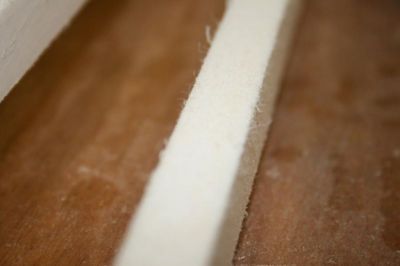
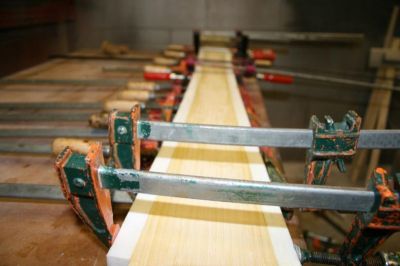
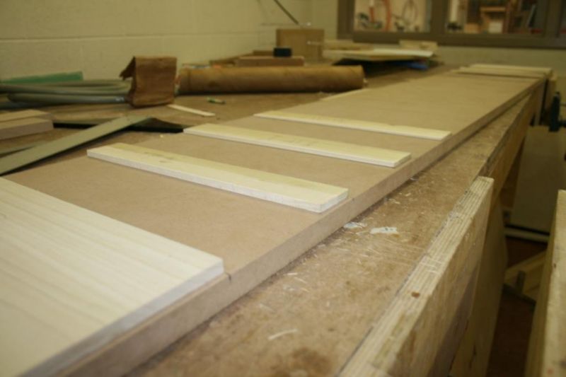
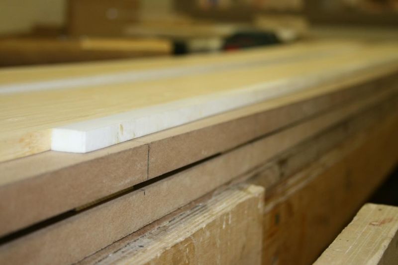
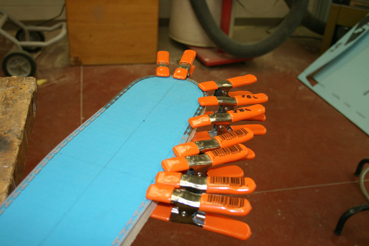
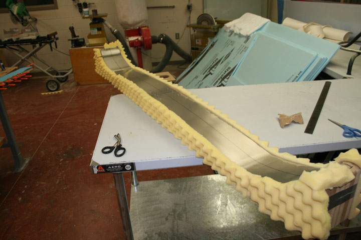
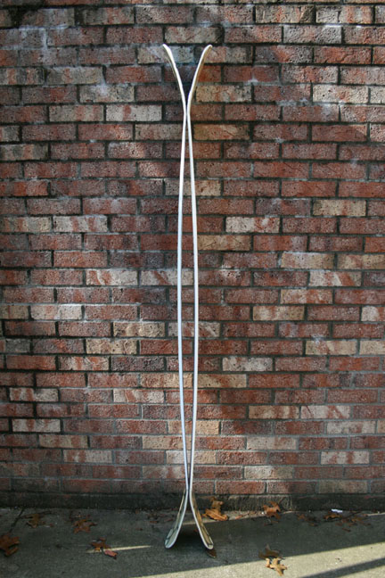
And on the fith day god made sidewalls. The material was warped so I had to figure out how to rip it into staight pieces. Answer..Epoxy, scrap wood, and clamps.

Image

Image

I forgot to take pictures while I epoxied the sidewalls onto my cores, but here is what I did. Sanded sides, flame treated with torch, and lightly sanded again. I then used West System 105 resin with 207 hardener to to bond the sidewalls on, clamping every 4 to five inches. The bond seemed great when I checked it a day or two later.

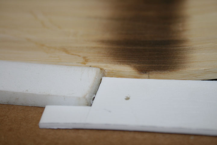
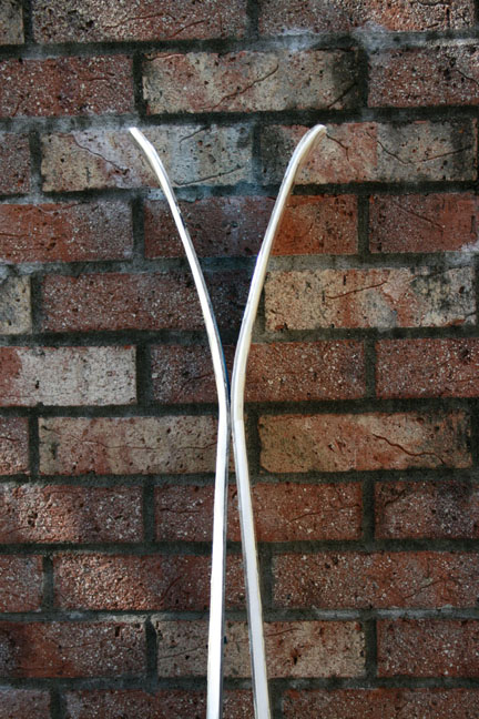
Apparenlty not though. One side wall started t delaminate when I ran it through the Planar a couple of time while the other held. we put the good core with sidewalls back on the mill to have a go at profiling.

The sidewalls held up to an initial trimming process we ran before the actual profiling process, but the side wall Delaminated at the start of the profiling. However we made a programming mistake and the CNC started the pass at about 1/4 in deep and hit the tip of the sidewall first. so this may have been the culprit, but the other core delamed ont the planar so its hard to tell.


Image
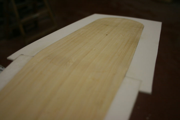
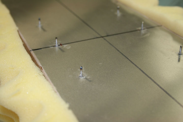
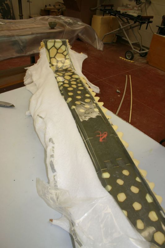
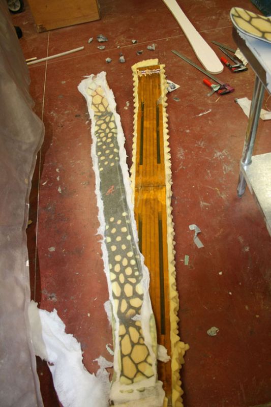
core w/sidewalls in a jig for screwing to bed


Image
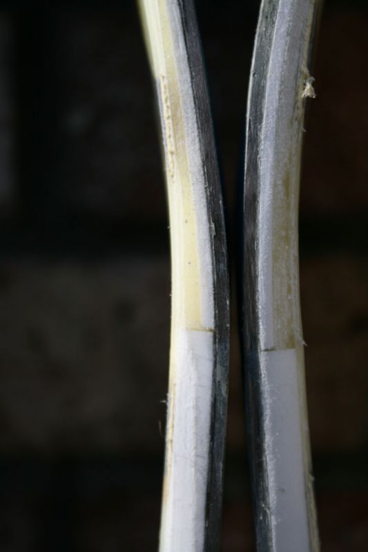
ouch! the frayed edges are from the initial trim process I mentioned above. The delamination happened when the bit dug into the end of the sidewall you can see there.


So any tips/suggestion from you experienced builders out there? It seemed like when I flame treated the p-tex it just made the surface smooth and unlikely to bond. did I heat it to long? or should I not flame treat at all and just abraid roughly?

more coming soon.
Last edited by jlutz05 on Thu Nov 06, 2008 11:34 am, edited 21 times in total.
jlutz05
Posts: 38
Joined: Fri Aug 29, 2008 10:57 am

Post by jlutz05 »

anyone know why the "[img]" inserts aren't working? The URL's work if you copy and paste them.
krp8128
Posts: 367
Joined: Fri Feb 23, 2007 1:57 pm
Location: Marcellus, NY

Re: school credit skis...The Recurve, or Maybe The ReCoast

Post by krp8128 »

Your tags are bad...

Image

For that image, use the code below with the extra space removed at the end.

[img]http://media.newschoolers.com/uploads/c ... 921114.jpg[/ img]
jlutz05
Posts: 38
Joined: Fri Aug 29, 2008 10:57 am

Post by jlutz05 »

got it, thanks^
knightsofnii
Posts: 1148
Joined: Tue Jan 08, 2008 6:02 am
Location: NJ USA
Contact:

Post by knightsofnii »

if the surface went smooth or shiny or changed appearance at all you probably went too slow or too high flame.

you should be able to see the surface MOVE but return back immediately after the flame passes, it doesnt take much

and sand it lots with a wet belt. dont over heat it or you change the properties and make it brittle. is it uhmw?

As far as profiling the uhmw, i'm not sure of the best way to do it.
One of our core guys is tasked with doing it like you do except with other tools.
Another core guy profiles a whole sheet by itself on a big cnc machine. we then rip it into strips.

if you have good vacuum hold down (you should with that techno isel) you can make a section to pop an entire sheet of sidewall material, then profile that down

but you need to take advantage of the vacuum suction that cnc provides.

block off all areas you're not using with like 3/4 or thicker mdf. something like 1/4mdf is thin enough that the vacuum goes right thru it so mke that your hold down area. make some jigs to hold down the tips. you might want to leave your core tips square so you can staple the corners down, then cut them off as the last step.

a staple or two at the end of each sidewall might help, build the sidewall with a little extra length and just cut it off at the end.
Doug
jlutz05
Posts: 38
Joined: Fri Aug 29, 2008 10:57 am

Post by jlutz05 »

thanks for the help.

I think I flame treated it just about liek you sadi, took the falme away as soon as I saw it swirl. Should I wet sand it after flame treating or before though?

I like your Ideas of profiling sheets of the sidewall material, that is interesting. are they hard to clamp on when they get thinner toward the tips?

As far as the vacuum table on the mill goes I'm not sure why we are not using it. I do not have the final say on the mill set-up, I am working with our shop guy here, and he seems to like screwing material down or making jigs etc. better. I'll ask him about it.
knightsofnii
Posts: 1148
Joined: Tue Jan 08, 2008 6:02 am
Location: NJ USA
Contact:

Post by knightsofnii »

by the way, everything looks awesome so far!

wish i had one of those cnc's

you could also try using the tape on your core/plastic, but it will be a hassle to clean it off like with your base.

maybe some 3m spray adhesive? i dont know, i know that most cnc bits dont like the plastic and it cuts off really stringy and can get caught up in the spindle, so keep an eye on it dont walk away from it. if that happens it can create lift on the part, just keep an eye on it, go in small increments with the tool path

but if you use anything with adhesive on the ptex, you're compromising its bondability and you'll hve to resand/flame it.
Doug
User avatar
zachjowi
Posts: 110
Joined: Sat Aug 26, 2006 10:41 am
Location: WI

Post by zachjowi »

that is really awsome,I made a kayak using the universities cnc router and have always wanted to make skis on the cnc router also.
jlutz05
Posts: 38
Joined: Fri Aug 29, 2008 10:57 am

Post by jlutz05 »

So...........Sidewalls and profiling round 2

I did acouple of test bond samples with some scrap sidewall and core material. After testing my samples I decided that a nice rough, almost fuzzy texture worked the best for me. I used a drum sander with some water to achive this. also a little hand sanding with 60 grit.

Image

I made sure I clamped those badboys on tight.

Image

After the epoxy cured it was time for profiling. I had previousy been working on a CNC here at school but The oporater left for good and I don't know how to use mastercamm etc. After a little searching in the forums I found and easy alternative which employs a thickness planer and a jig (thanks for the help mark and muramo).

In my opinion this method seems mutch easier than that of the hand router with a crib and bridge.

Basically you take two pieces of MDF and place shims inbetween either end. The thickness of the shims should equal the difference between your max core thicknesses and tip/tail thickness.

screw the upper mdf sheet to the bottom at the points where you core becomes flat for binding mounts

After the jig is complete secure you cores to it and run the whole contraption through the planer.

Here is the bottom board with shims glued on. I added extra shims to prevent bowing under pressure.

Image

upper mdf piece screwed on with core on top. I used double sided tape to hold the cores in place. I also made sure that both cores could fit on the jig at once.

Image

here are the tips after profiling they are 2mm, or 3mm if those are actually the tails.

Image


In retrospect I would not use double sided tape anymore. It was really hard to remove the cores from the jig. It took me forever, I used lots of acetone, and risked damaging the cores.

I have a question for all of you guys regarding tip spacers. What should I do about the difference in thickness between my core and spacers?

The is 2 or 3 mm more core material than tip spacer material where the sidewalls end. Does anyone else have this problem and how do you solve it?

Image

Image

For the graphichs I am planning on using a laser cutter on some kevlar. I plan to do a cellular pattern which is more dense towards the bindings and thinnner towards the tips/tails.

Hopefully this will provide extra stiffness to the ski towards the boot while providing a cool graphic at the same time. Here is a little test section of kevlar.

Image
doughboyshredder
Posts: 1354
Joined: Mon Sep 17, 2007 7:37 pm

Post by doughboyshredder »

Really nice work! It's great to someone undertaking this project with great attention to detail.
What should I do about the difference in thickness between my core and spacers?
Try laminate bulkers. Info at the bottom of this page. http://www.fibreglast.com/showproducts- ... e-157.html
ben_mtl
Posts: 583
Joined: Mon Mar 31, 2008 1:47 pm
Location: Sherbrooke, Quebec
Contact:

Post by ben_mtl »

you can also taper the edge of your core on tip and tail areas so it matches the tip spacer thickness.
rockaukum
Posts: 558
Joined: Fri Nov 03, 2006 9:23 am
Location: Placerville area

Post by rockaukum »

Cut extra glass to "fill" the difference. Progress looks good.
ra
jlutz05
Posts: 38
Joined: Fri Aug 29, 2008 10:57 am

Post by jlutz05 »

Ok, I finished my skis up before my christmas break and got to ski them for a month or so which was sweet. I didnt document th elast half of my process quite as well, but here is what I have.


after the cores where profiled I needed to prebend. Due to the early rise tip and tail the cores where soomewhat thick at the bend points, making it more diffucult. After a little google-ing I decided heat was the best way to bend bamboo, so I used a heat gun along with a simple jig made out of pipes and threaded rods.
Image

results....
Image

One problem was an offset between tip spacer height and core/sidewall height. I used microfiber epoxy thickener to fill in this gap during lay-up. I put it on the core slightly before I started the main lay-up process so it would have time to set up a little. It ended up working well.
Image

botom of pre-bent cores, tip spacers are tacked on with super glue.
Image

standard edge tack-on with super glue and mini clamps. I heated the edges and bent them with pliars. I thought this was the least controlled step in my ski construction, the edge bending is the thing I really need to become more effecient in (any suggestions/tips?).
Image

For my graphics I laser-cut kevlar with a sheet of vellum paper over top of it. The thought was to create a graphic that helped the ski become stiffer under foot and more flexible towards the tip/tail. As an afterthought this was a stupid idea because it wastes a lot of kevlar

kevlar with vellum lightly spray adhesived on
Image

sorry, I cant find the pictures I took of the laser doing its job.... here is the result though. I had to do each ski in three sections due to length of the laser's bed.
Image

I used aluminum flashing as my mold surface, I attacthed it using spray adhesive and a vacuum bag. The yellow foam is there to prevent the vacuum bag from sucking itself shut on the side of the mold.
Image

alignment pins
Image

I should have checked out the schools vacuum system earlier the bag was terrible, and full of holes which I tried to patch. I would have just bought some plastic and made one but it was too late at this point.
Image

I ended up getting around 11 psi ont the first ski, not too bad considering the condition of the bag. I used a standard electric blanket for heat, didnt have a thermometer though.
Image

I guess I was getting sleep deprived towards the end of the semester because I started making really stupid mistakes. I didnt make my mold very wide and neglected to make a "bag" out of painters palstic. I also used way too mutch epoxy, which I expected I would since this was my first lay-up. Anyway the result was a solid ski/mold combo when I took it out of the vac bag.
Image

Image

This is what my mold looked like after an hour fight with me, two other guys, and some hammers/chisels.
Image

I was pretty discouraged at this point because I had two more nights to get the complete pair of skis finished before I left school for break. Anyway I worked hard and salvaged my mold, with some scrap from the plastic shop.
Image

The next lay-up went more smoothly except for the fact I got food poisoning from one of our dinning halls just before I started. Needles to say that sucked, epoxy resin fumes and food poisoning don't mix well.
Image

I trimmed them on a large band saw, and then used a drum sander to even things up. for the sidewalls I clamped the ski down, and used a hand router with a beveled edge and bearing spacer.
Image
if I remember correctly the weighed 5.2 and 5.4 lbs
tip/tail length: 185
running length: 135
waist: 89
max width: 135

compared to 178 rossi scratch brigades
Image

Image

Image

edges fit snuggly to base along the side cut. There were some minor gaps near tighter radii.
Image

definatly the largest skis I have been on.
Image

lots of camber!!
Image

early rise tips/tails
Image

Here you can see the area which was filled in by the epoxy thickener.
Image

Now the fun part!! They ski great, did mostly what I wanted them to do. while skiing them was a little awkward at slow speeds, you could really snap some slalom race ski style turns at a faster pace.
Image

Also great for switch skiing, the early rise tail made cathing and edge back there seem like less of a threat.
Image

I got to ski a couple inches of pow in them but nothing too deep. Anyway they were definatly fun in the soft stuff, you could really pop out of the pow when you wanted.
Image

spinning was also fun....a little hard due to lentgh, but the symmetric design helped out.
Image

complaints are: too flexible under foot, a little awkward at slower speeds, a litttle heavier than I would like, don't hold on ice very well.

Over all this has been a sweet experience building and skiing my own ride! I plan to try and make some more, in the near future. Thanks too the creators of this site, everybody in the forums, and all the people at VT who helped me with this project!
twizzstyle
Posts: 2204
Joined: Tue Mar 07, 2006 8:25 pm
Location: Kenmore, Wa USA

Post by twizzstyle »

Looks like a very good project, I am jealous of the CNC work :(

Very interesting ski shape too, that is a LOT of sidecut!
twizzstyle
Posts: 2204
Joined: Tue Mar 07, 2006 8:25 pm
Location: Kenmore, Wa USA

Post by twizzstyle »

Also I am in love with your graphics, the laser cut kevlar looks great.
Post Reply