
I see the 2 red wires that are crimped together and connected to the left buss bar. I assume that one each of those wires goes to one each of the heaters and provides a 120 volt leg to the heaters. There's a red wire that comes out of the lower left of the photo. Where does it come from and here does it go? What are those brownish colored wire looking things that look like bare copper in the lower left corner? Where is your thermocouple wire? Where do the main black and red wires that connect to the main lugs in the box come from? Have you used a voltmeter to check and see what kind of voltage you actually have at each buss bar/terminal block? Yes, if the one of the heaters was shorting to ground, it should blow the fuse in the yellow fuse link... but, I think that two properly operating 10 amp heaters should blow the 12 amp breaker/buss bar fuses anyway. Are the buss bars shorting to the metal box? It looks like all the wiring between the breaker and the buss bars has been cooked and discolored. Correct me if I'm mistaken, but didn't you say that the heaters and the PID's were functioning at some point. If so, did you change anything about the wiring between then and the big melt-down?
Sorry about all the questions, but maybe one of them will help to lead to some kind of answer.
G-man
Oh... edit to add: Did the fuses blow and melt down as soon as you threw the switch on the breaker, or did the melt-down occur at some other time during operation?
electrical gurus
Moderators: Head Monkey, kelvin, bigKam, skidesmond, chrismp
Much like G-man, I'm having a bit of trouble following the wiring, but I do notice a few things:
- 1. The yellow fuse holders going into the PID have really "rough" ends. Cut these back, and either tin these with solder or use crimp-on connectors. Frayed or loose wires at connections can cause overheating or excessive current draw.
2. The yellow fuse holder to red wire connection, is this soldered or just twisted together and taped? It should really be soldered if you are going to do it that way, for the same reasons as above and incase you ever tug on the wores outside of the box, you don't want a live wire to touch the box...(breakers should trip, but better off not to test them).
-
bobbyrobie
- Posts: 124
- Joined: Wed Sep 17, 2008 9:17 pm
G-Man
you are correct the 2 red wires crimped together are the 2 other 120 volt legs to each heater. and that lower red wire just connects to the yellow fuse holder. the brownish color wires are the 2 TC's that come from the PID's. the main wires that come from the top right? they are attached to a 240volt plug male plug that i plug into the wall. the reason those buss bars are kinda discolored is because it had melted down a previous time. were the wires connect in the male plug the ground insulation some how rubbed on one of the 120v hot leads.i thought i was good after i fixed that so i threw on some new inline fuses and tryed again. If the heaters are pulling 20 amps total, that would be 10 amps from one hot 120v and also another 10 amps from the other hot lead right? well i just threw a voltmeter on on it and im reading 117.5V on one side and 119.5V on the other side. everything works great until i start putting down alot of heat. i had it running for at least an hour at 120 degrees with no problems. shop was around the 65-70 degree range. but once i applied pressure to the press along with more heat, problems started happening. so everything was functioning fantastic to begin with. i wonder if applying pressure is causing something? most likely not though.
krp8128
the yellow fuse holders are going to the heaters; the PIDs do not have any fuses attached directly to them. Or did you mean the SSRs? they attach to those. They are just twist tied together with electrical tape. i will solder those and get rid of any frayed connections that are present on the SSRs. Shouldn't hurt to get rid of any possible variables.
G-man wrote:I see the 2 red wires that are crimped together and connected to the left buss bar. I assume that one each of those wires goes to one each of the heaters and provides a 120 volt leg to the heaters. There's a red wire that comes out of the lower left of the photo. Where does it come from and here does it go? What are those brownish colored wire looking things that look like bare copper in the lower left corner? Where is your thermocouple wire? Where do the main black and red wires that connect to the main lugs in the box come from? Have you used a voltmeter to check and see what kind of voltage you actually have at each buss bar/terminal block? Yes, if the one of the heaters was shorting to ground, it should blow the fuse in the yellow fuse link... but, I think that two properly operating 10 amp heaters should blow the 12 amp breaker/buss bar fuses anyway. Are the buss bars shorting to the metal box? It looks like all the wiring between the breaker and the buss bars has been cooked and discolored. Correct me if I'm mistaken, but didn't you say that the heaters and the PID's were functioning at some point. If so, did you change anything about the wiring between then and the big melt-down?
Sorry about all the questions, but maybe one of them will help to lead to some kind of answer.
G-man
Oh... edit to add: Did the fuses blow and melt down as soon as you threw the switch on the breaker, or did the melt-down occur at some other time during operation?
Good point krp. I get pretty obsessive with my connections in that I first remove and discard the plastic ferrule from the connector, then slide an inch long piece of shrink tube down the wire a few inches, add a little flux to the stripped wire end, crimp the connector on the wire, solder the connection and let it cool, then slide the shrink tube in place and shrink it down. Makes for a very clean and strong connector, but like I said, maybe a bit obsessive. A small hair dryer works well on the shrink tube. I get the shrink tube in lots of different colors and in 3 foot lengths... gotta keep things color coordinated, ya know. Here's a couple of pics of the driver board enclosure on one of my cnc's:The yellow fuse holders going into the PID have really "rough" ends. Cut these back, and either tin these with solder or use crimp-on connectors. Frayed or loose wires at connections can cause overheating or excessive current draw.
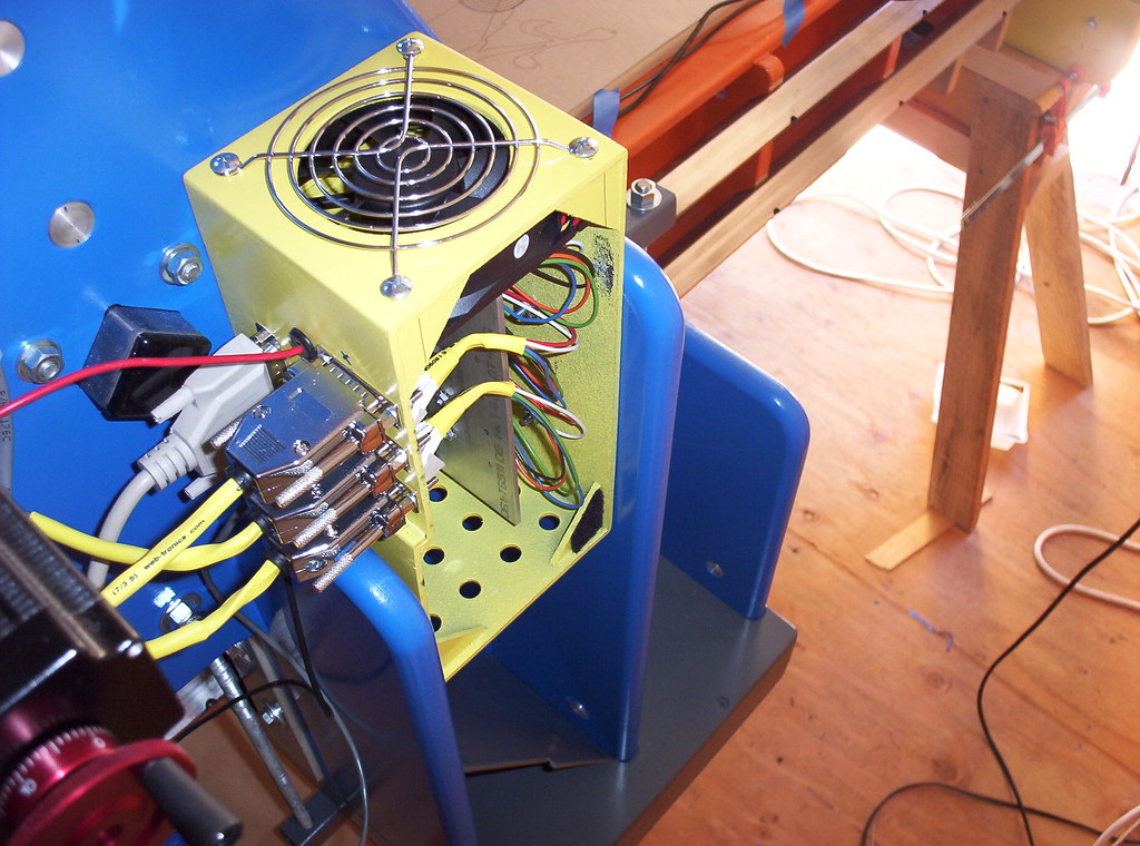
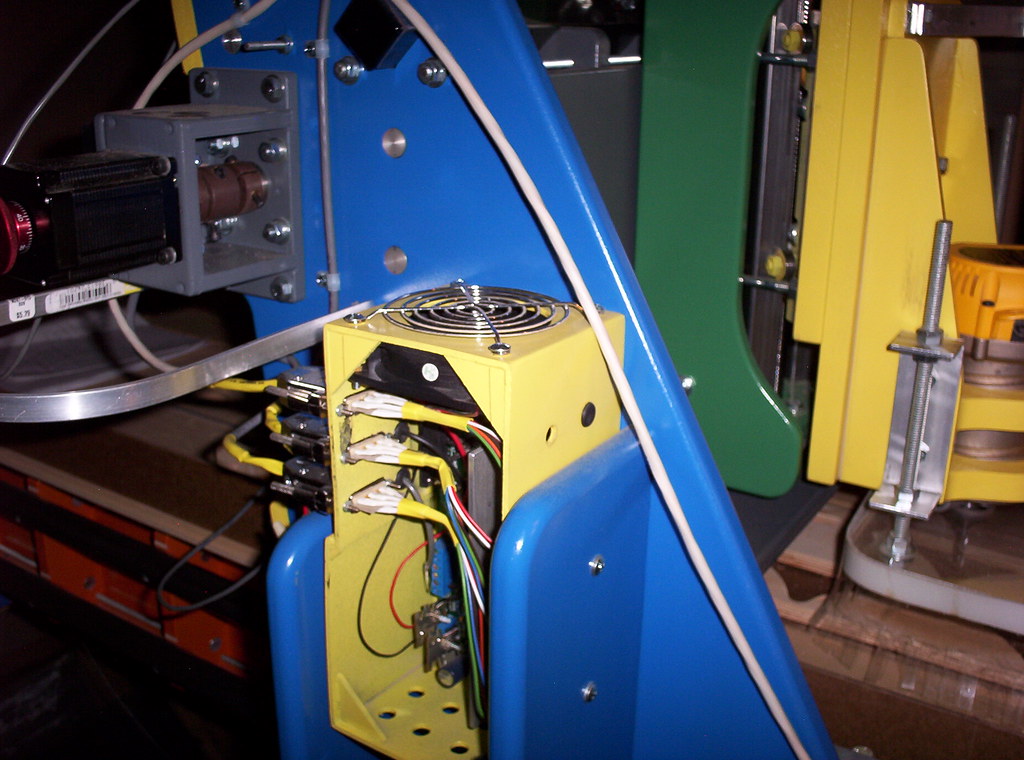
There's 24 little tiny soldered connections inside each of those silver connectors. The enclosure is made from sheet ABS from Tap Plastics (no shorting on a plastic enclosure). Wiring jobs that are clean and neat help to avoid problems from the start, and clean and neat makes trouble shooting much easier when a problem does show up... IMHO.
G-man
This I'm just not sure about. I'll try to explain. Since normal house current is alternating current, the actual direction that the electrons flow reverses direction 60 times per second (60 cycles). Put another way, the hot wire has a negative charge alternating with an equal positive charge, and the polarity of the hot wire reverses 60 times per second, meaning that the voltage is positive for 30 cycles per second and negative for 30 cycles per second. The current returns to ground via the neutral wire. With most 240 volt circuits, there is no neutral wire/lead. When one hot wire is negative, the other is positive, so the two hot wires complete the circuit together because they are "out of phase". So, in essence 240 volt wiring is powered by 2 - 120 volt hot wires that are 180 degrees out of phase. So, if one leg of the 240 circuit is acting as the neutral leg at any given time, that means that the other leg (positive leg at that moment) is providing all 20 amps to the circuit demands for 30 cycles per second. This says to me that both legs are individually providing the full circuit demands during their 30 cycles per second, and therefore would need to be fused for the full 20 amp load. Again, I'm just not sure about this. Like I said, I'm just a lowly grasshopper in the discipline of electronics.If the heaters are pulling 20 amps total, that would be 10 amps from one hot 120v and also another 10 amps from the other hot lead right?
This is valuable information. Since your system does function without problem when under limited demand, that says that you probably don't have a short circuit or circuit continuity/polarity issue. It more indicates that as the PID's tell the SSR switches to close more frequently and for longer periods of time (in order to get the blankets up to a higher temperature), the increased current demands are more than your circuit's thermal protection can handle. 120 degrees F isn't much to ask of your system. Because you are using two heaters at 10 amps each, at 120 degrees, the SSR's that control the heaters may not actually be closed at the same time very often, therefore, the system may not be drawing the full 20 amps very often, and even then, it may be only for a few seconds. As you increase the temperature demands, the on-time overlap of the SSR's increases and the wires and fuses have a greater chance to heat up. Also, it looks like your wire gauges change from smaller to bigger at different places. It's better to try to keep them uniform. Don't size the wire to the lead size that comes off the heater... go bigger. Remember, the heater is supposed to get hot, but your circuit wiring is not.once i applied pressure to the press along with more heat, problems started happening.
All this doesn't mean that you don't have a shorting issue when your system is under greater pressure, but I think this is a less likely option. However, as I and others have pointed out, you'll still likely be better off in the long run if you go back and tidy up your wiring and connections. You've taken a number of risks to yourself and your components so far, and I say you've both been rather lucky up until this point. Don't take it personally... we all learn from each other, both through our successful and not-so-successful endeavors.
G-man
Yes, I meant to say SSR.bobbyrobie wrote:
krp8128
the yellow fuse holders are going to the heaters; the PIDs do not have any fuses attached directly to them. Or did you mean the SSRs? they attach to those. They are just twist tied together with electrical tape. i will solder those and get rid of any frayed connections that are present on the SSRs. Shouldn't hurt to get rid of any possible variables.
G-man, that's not obsessive, that's prudent on work of that caliber. I used to be a little sloppy with some of my connections with the "intent" to go back and fix them once I knew everything worked. After I worked in an R&D department for 7 months it quickly became clear how big of a difference one poor connection can make. Now it's all solder and shrink tube on my projects the first time around.G-man wrote: Good point krp. I get pretty obsessive with my connections in that I first remove and discard the plastic ferrule from the connector, then slide an inch long piece of shrink tube down the wire a few inches, add a little flux to the stripped wire end, crimp the connector on the wire, solder the connection and let it cool, then slide the shrink tube in place and shrink it down. Makes for a very clean and strong connector, but like I said, maybe a bit obsessive. A small hair dryer works well on the shrink tube. I get the shrink tube in lots of different colors and in 3 foot lengths... gotta keep things color coordinated, ya know. Here's a couple of pics of the driver board enclosure on one of my cnc's:
There's 24 little tiny soldered connections inside each of those silver connectors. The enclosure is made from sheet ABS from Tap Plastics (no shorting on a plastic enclosure). Wiring jobs that are clean and neat help to avoid problems from the start, and clean and neat makes trouble shooting much easier when a problem does show up... IMHO.
G-man
P.S. I need that CNC...
-
doughboyshredder
- Posts: 1354
- Joined: Mon Sep 17, 2007 7:37 pm
I would rewire without all those fuses, and get rid of that breaker. If you are plugged in to the wall you are already on a breaker. At most you could put little 1/2 amp fuses on your pid's, but really I think that's pointless.
I would guess you may have actually pierced one or both of your blankets, and have a short somewhere. Of course your heater blanket is just one big short circuit causing the wire to get hotter.
Take the time to remove one blanket from the press and set it up alone, see how it works, same with the other one.
G-man is correct. A 240v 20amp circuit is not 10 amps on each line, it's 20amps because of phasing.
I totally agree with this entire statement.I would rewire without all those fuses, and get rid of that breaker. If you are plugged in to the wall you are already on a breaker. At most you could put little 1/2 amp fuses on your pid's, but really I think that's pointless.
Good trouble shooting approach.Take the time to remove one blanket from the press and set it up alone, see how it works, same with the other one.
I'm going to be a nerd here and post a couple links:Of course your heater blanket is just one big short circuit causing the wire to get hotter.
http://en.wikipedia.org/wiki/Nichrome
http://en.wikipedia.org/wiki/Short_circuit
A heat blanket is really kinda the opposite of a short circuit. With a true short circuit, there is an open path to ground with very little resistance. Ohm's law says that amps = volts/resistance. So if you have a voltage potential of 240 volts and just 1 ohm or less of resistance (such as in a true short circuit), 240 amps of current are capable of flowing through the circuit, unless something interrupts the flow of current, like a blown fuse, a tripped breaker, or a melted wire or other component. With a heat blanket, there's a lot of resistance which limits the flow of current to ground. It's true that there's a lot of heat given off in both situations, but the amount of amperage involved is quite different. By the definitions of electric potential (volts) and current (amps), work is done at a rate of one watt when one amp flows through a potential difference of one volt, therefore amps = watts/volts. So, a 2400 watt heat blanket wired to 240 volts is only going to draw 10 amps versus the 240 amps or more that a short circuit would draw.
Sorry guys... I've been away from the electrical end of things for awhile and I'm enjoying this little refresher. Okay, the nerd is going to bed.
G-man
-
doughboyshredder
- Posts: 1354
- Joined: Mon Sep 17, 2007 7:37 pm
Ahh, thanks. I have been kind of confused about how heat blankets and just plain heat wires work. I don't see how it is changing resistance to ground on a 240v blanket, since there is no ground, I guess just increasing the resistance between both hot legs? I thought of it as a short since the two hot wires are connected together causing the heat, but I understand what you're saying, a short is indicative of zero resistance, and the heat wires are actually heating up because of the high resistance. Cool.G-man wrote:I'm going to be a nerd here and post a couple links:
http://en.wikipedia.org/wiki/Nichrome
http://en.wikipedia.org/wiki/Short_circuit
A heat blanket is really kinda the opposite of a short circuit. With a true short circuit, there is an open path to ground with very little resistance. Ohm's law says that amps = volts/resistance. So if you have a voltage potential of 240 volts and just 1 ohm or less of resistance (such as in a true short circuit), 240 amps of current are capable of flowing through the circuit, unless something interrupts the flow of current, like a blown fuse, a tripped breaker, or a melted wire or other component. With a heat blanket, there's a lot of resistance which limits the flow of current to ground. It's true that there's a lot of heat given off in both situations, but the amount of amperage involved is quite different. By the definitions of electric potential (volts) and current (amps), work is done at a rate of one watt when one amp flows through a potential difference of one volt, therefore amps = watts/volts. So, a 2400 watt heat blanket wired to 240 volts is only going to draw 10 amps versus the 240 amps or more that a short circuit would draw.
Sorry guys... I've been away from the electrical end of things for awhile and I'm enjoying this little refresher. Okay, the nerd is going to bed.
G-man
Yes, 240 volt wiring has always been a little difficult for me to get my head around, especially after working a bunch on DC circuits and 120 volt circuits. It has always seemed so weird that a 240 circuit has no dedicated neutral wire. Here's a link that helped me to get a better sense of how 240 works:
http://www.nojolt.com/Understanding_240 ... uits.shtml
G-man
http://www.nojolt.com/Understanding_240 ... uits.shtml
G-man
-
doughboyshredder
- Posts: 1354
- Joined: Mon Sep 17, 2007 7:37 pm
That really explained a lot. I also have a bunch of experience with low voltage. AC and DC, not much with 240. Interesting stuff.G-man wrote:Yes, 240 volt wiring has always been a little difficult for me to get my head around, especially after working a bunch on DC circuits and 120 volt circuits. It has always seemed so weird that a 240 circuit has no dedicated neutral wire. Here's a link that helped me to get a better sense of how 240 works:
http://www.nojolt.com/Understanding_240 ... uits.shtml
G-man
-
bobbyrobie
- Posts: 124
- Joined: Wed Sep 17, 2008 9:17 pm
I started getting to work on the electrical enclosure today. took the blankets off the press and everything looks fine. so theirs no shorts within the heater blankets them selves. So i am not really sure whats going on. so i have started to rewire everything and cleaning it up. The breaker should be able to protect the blankets. i shouldn't really need to fuse them. im curious to see other peoples wiring diagrams for their heaters and if they differ any from what i am doing?
The limited layout drawing that you included in your first post was missing a lot of details, but your pictures eventually helped to fill in some of the gaps, but not all. One glaring missing piece is the fact that there only two small wires (going to the PID controllers) connected to the ground bar on the enclosure, yet you have noted that 'everything' is grounded. I still don't see where you have grounded the heat blankets.im curious to see other peoples wiring diagrams for their heaters and if they differ any from what i am doing?
You simply can not diagnose an intermittent short circuit in a pressurized heater blanket just by looking at the non-pressurized heater. I'm reasonably confident that you don't have a short in the heater blankets, but I certainly wouldn't bet my life on it, and that's exactly what you are doing by running with such an unknown problem without proper grounding. I'm not wanting to be harsh on you in particular, but I do want to make a point to anyone who wants get into making their own skis that ski building can certainly be a whole bunch of rewarding fun, but the venture can also quickly get into unfamiliar and dangerous territory that can suddenly get someone seriously injured or killed. We're working with significant pressures and big potential current loads, especially if our bodies should happen to become the easiest path to ground. The electrical system needs to be well engineered and properly constructed. The structural loads on presses should be calculated so as to be sure that the press and all it's welds and fasteners can take the applied load. Steel fasteners fail when they get loaded with a force that is beyond their load bearing threshold. All that stored energy has to go somewhere, and anything in it's path is in serious trouble.took the blankets off the press and everything looks fine. so theirs no shorts within the heater blankets them selves.
And that's okay. But it's important to recognize when it's time to get a trained eye on the project, not just a group of guys on a forum who are looking at pictures late at night when they should be sleepin'.So i am not really sure whats going on.
Again, this is electricity. We don't like 'should' when it comes to electricity. 'Should' means there's still the possibility of loud noises, sparks, fire, and smoking hair. It's kinda like saying, "Well it should fly... wanna go for a ride?" Electricity is just another form of math, and, as with all math, it either is, or it isn't. Get familiar with the formulas, plug in the numbers, and do the math. Then you'll be saying, "it will", rather than, "it should".The breaker should be able to protect the blankets.
Regarding other folks wiring strategies for their heaters... from what I can see from your pictures, it looks like you have the basic circuit routing correct, so other drawings would likely look very similar to what is represented in your pictures. It's the execution of the actual assembly that needs more work, and I realize that you're moving in that direction. It's relatively clear that you could use some more experienced help. I just think that that person should be sitting next to you during assembly, rather than attempting to communicate via the internet.
It's late, so I'll spare you my speech about how toxic fiberglass dust particles are and why you should always wear a good respirator mask when cutting and grinding on cured glass... and how no matter how careful you are, that *#&$ gets everywhere.
G-man (grouch-man?)
-
doughboyshredder
- Posts: 1354
- Joined: Mon Sep 17, 2007 7:37 pm
g-man, there is no way to ground a 240v heater blanket as far as I know. Not possible on mine, I have two hot leads and nothing besides rubber anywhere else. What should be grounded is your entire press. And, I don't think mine is except for through the ground on the hydraulic rams. Hmm, I think I should put a grounding strap on there.
Thanks doughyboy. Yes, when I re-read what I had submitted last night, I realized that I hadn't clearly said what I meant to get across, but it was really late and I was not thinking too well. I meant to say that the press and any aluminum pressing layers should be grounded so that any wayward current from the heaters would have a safe path to ground. I know that you know this, but for anyone who's not sure what I mean, a ground wire should be attached to the press and to the pressing layers, then back to the ground bar in the control box. This way, if a press part or a sharp edge on a pressing layer should pierce a heat blanket and cause a short circuit, the sudden unrestricted current flow will immediately trip the circuit breaker and alert the operator that there is a problem that needs to be identified. If a press layer that wasn't grounded were to pierce a heat blanket, no current would flow through the press layer (due to the press layer not having a path to ground), so there would be no short circuit and no evidence of a problem, until such time that some grounded object came along and touched the pressing layer, at which time, unrestricted current would immediately flow through that object until such time that the current flow reached the rated protection value of the circuit breaker, causing the circuit breaker to trip. If the breaker size is 30 amp at 240 volts with a human body providing the path to ground... ugg... I don't even want to think about that scenario.
I had asked the question in a an earlier post if a 240 volt heater came with a ground wire. Now that I think more about it, doughboy is correct, there is no feasible way to ground a non-conducting material such as the silicone in a heat blanket. Only conductive materials can be grounded , duh.
G-man
Edit to add: Because a heat blanket houses a long length of high resistance wire, any short circuit of a heat blanket would not truly provide a path for 'unrestricted' flow of current as I had stated above. The resistance of the wire would limit current flow to some degree which, of course could be calculated.