Feed-Planer retro-fit, core profiler

For discussions related to designing and making ski/snowboard-building equipment, such as presses, core profilers, edge benders, etc.

Moderators: Head Monkey, kelvin, bigKam, skidesmond, chrismp

Post Reply
petemorgan(pmoskico)
Posts: 85
Joined: Thu Dec 22, 2011 8:41 am
Location: Tacoma, Washington, USA! USA!
Contact:

Feed-Planer retro-fit, core profiler

Post by petemorgan(pmoskico) »

I am in the midst of retrofitting my planer. the concept is pretty similar to the ski-builder's router/bridge/rail method. Though I got this idea from Igneous skis out in jackson, WY. The planer moves up on its stock pillars via skateboard wheels running along 2 rails that dictates that thickness of the core.

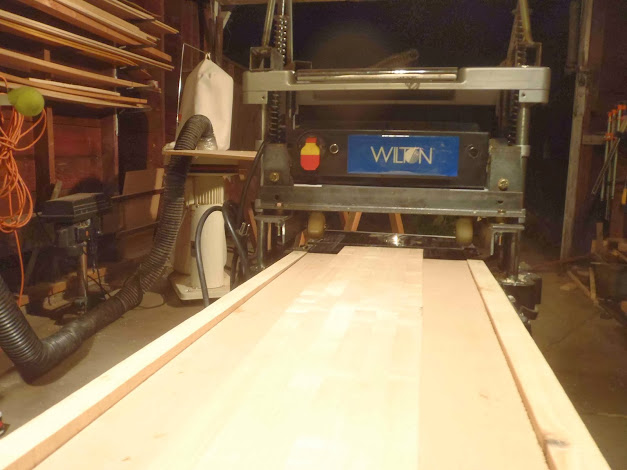
this has been a project of a constantly evolving design, because it boiled down to what planer geometry was and how to retro fit it to meet my needs. one of my critera was to always be able to reverse the "damage" to use the planer as its original use.

i didn't know if the planer head was heavy enough to produce enough downward force to actually cut anything... normally the head is sandwiched between two bolts, but i needed to upper bolt to be removed so the head could travel up freely. the lower bolt would still be adjustable to dictate the lowest position of the planer head.

i removed the upper bolt and tried running a simple plank through it , but unfortunately the weight of the planer head wasn't enough to produce enough downward force and the head lifted up not cutting anything.

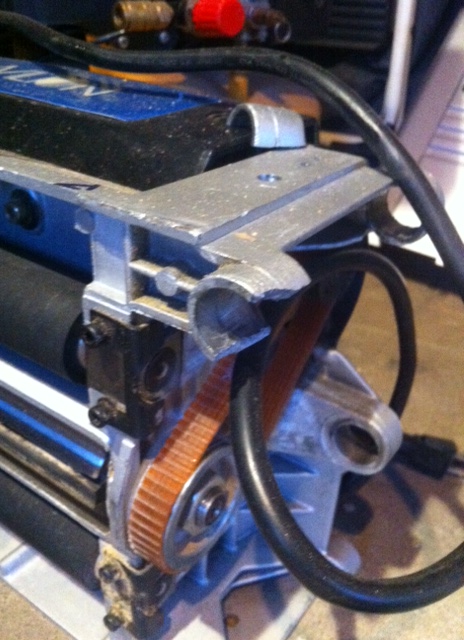
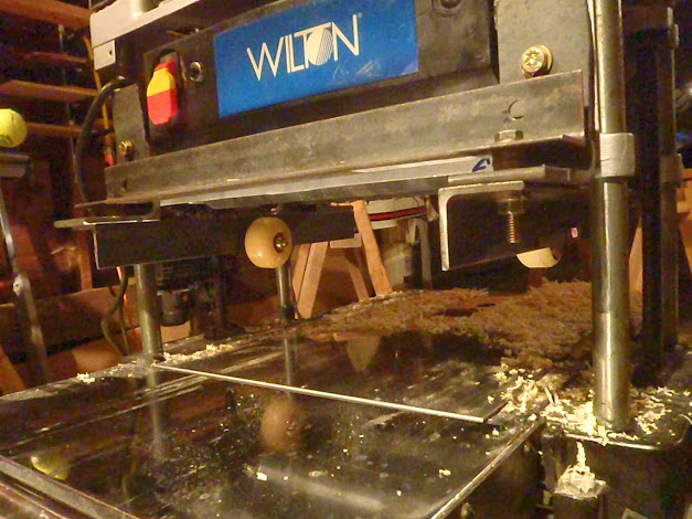
so back to the design table: i had to produce more downward force in order to actually plane a sliver of wood. pretty cool considering that the planer head weighs probably 75 pounds. the tolerance and rigidity of the front roller is good, thanks WILTON tools. and i think the forces produced by the wildly fast and powerful blade of the planer head added to the head lifting up.


igneous uses a snow-mobile shock for some of the downward pressure, and i remember their vertical pillars were more sophisticated.
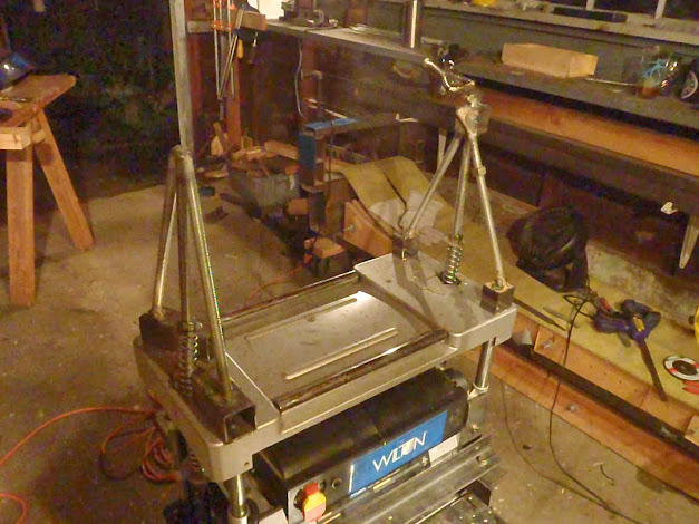
for my extra downward force i used 2 springs that that are held down from above, The springs are beefy and adjustable via a nut/washer on threaded rod. i built a freestanding triangle with threaded rod in the middle for the spring to adjust.


Image

Image

Image

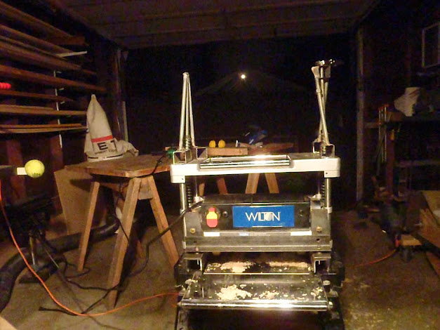
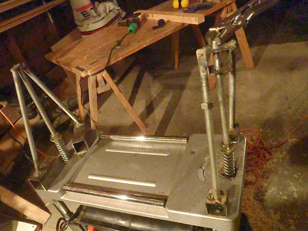
the trial angular shapes are merely bolted to the top of the planer to make for easy removal and turning the planer back into its original shape

notice my turning handle, the planer moves up and down via my vise grips which are an extension from the original. the right one took my thinking then the left one, especially because my design criteria was to make it reversible. some welding in sued, but legal
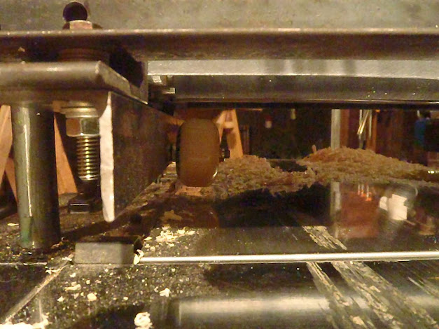
Image

Image

Image

Image

tapered rails

Image

The core sitting in between the rails.


The downward force produced by the springs works well if i am just doing simple planing without the wheels or a jig or anything like that. like as if it were just the top bolt removed and the springs pushing down.

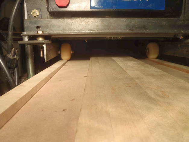
The problem right now is that when the planer head is fully resting on the skateboard wheels and trying to move up past more than 4 or 5 millimeters, there is a lot of of friction and it is causing the core to get stuck inside the planer which causes the feed rollers to "skip" or "burn rubber" on the wood because they aren't strong enough to pull that kind of force.

i am trying to figure out how to reduce friction. For one the skateboard wheels are just bolted on with a nylon locking nut. :c\ which isn't great.

i might be just going back to the router/bridge method
Last edited by petemorgan(pmoskico) on Wed Oct 09, 2013 6:27 am, edited 1 time in total.
gozaimaas
Posts: 663
Joined: Fri Feb 10, 2012 4:17 am
Location: Nagano Japan

Post by gozaimaas »

So the blade and the feed are on the top? Its always going to be a struggle getting the core to slide.

All I can recommend is to make a profiling bed with a sheet of nylon or something slippery on the bottom and lubricate it when you use it
User avatar
falls
Posts: 1458
Joined: Tue Oct 27, 2009 5:04 pm
Location: Wangaratta, Australia

Post by falls »

http://m.aliexpress.com/item/626348192. ... sitedetail

Maybe mount the sled on bearings to run it through the planer
Don't wait up, I'm off to kill Summer....
User avatar
vinman
Posts: 1388
Joined: Fri Nov 09, 2007 4:16 pm
Location: The tin foil isle
Contact:

Post by vinman »

Make a bed out of some kind of roller bearing like the small round bearings used on some out feed tables/supports for wood working. Or a set of rollers for woodworking.

http://toolmonger.com/2008/02/04/keep-o ... -bearings/
Fighting gravity on a daily basis
www.Whiteroomcustomskis.com
MadRussian
Posts: 712
Joined: Thu Sep 30, 2010 12:32 pm
Location: USA

Post by MadRussian »

I have not failed. I've just found 10,000 ways that won't work.
Thomas A. Edison
petemorgan(pmoskico)
Posts: 85
Joined: Thu Dec 22, 2011 8:41 am
Location: Tacoma, Washington, USA! USA!
Contact:

Post by petemorgan(pmoskico) »

well.... Apparently the planer head was not designed for this type of abuse... i cracked all 4 of the lower slid fit holes on the planer head that allow the planer head to slid up and down on the greased up pillars. (there are 8 total, but only the bottom ones cracked with one of them completed sheering off.

i have not failed... i just found one way that definitely does not work. this does free this planer head up from its normal 9-5 (or any use at all) so maybe i can free my own creativity from the constraints of this structure and create something that is more innovative... maybe a CNC head?

this might have to take a back burner, its that time a year again to actually build skis
twizzstyle
Posts: 2204
Joined: Tue Mar 07, 2006 8:25 pm
Location: Kenmore, Wa USA

Post by twizzstyle »

Wow, bummer! If it was sliding on the normal guides, why was it loaded any more than normal? Or did you try to take off too much in one pass? This seemed like a great idea.
petemorgan(pmoskico)
Posts: 85
Joined: Thu Dec 22, 2011 8:41 am
Location: Tacoma, Washington, USA! USA!
Contact:

Post by petemorgan(pmoskico) »

Image

twizz, i dont know exactly how it happened. I am guessing just the head lifting up while pushing material through and having the spring pushing down put some unequal forces on the posts. It seemed like the entire structure tilted slightly away from the feed while feeding thru.

win some you lose some
Post Reply